
| Project: Schools Wind Tunnel 20th December 2010 The intention of this project was to see if I could develop a desktop-size wind tunnel that might be usable in schools or colleges. By background I'm an aerospace engineer and I thought that this might be somewhere I could add some value. I did manage to get a working wind tunnel although I didn't manage to get some of the experiments I'd hoped for working. I made the tunnel with laser-cut plywood from Ponoko and the models for the test section were all 3D printed at Shapeways. 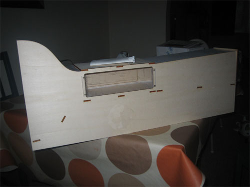 Wind tunnels are not new, they've been around since the dawn of flight. They are designed to allow testing of a model, be it a whole aircraft (or building, bridge, antenna, ...) or a part of one, like a wing section in a uniform, controllable air flow. This can be important because it can allow direct & repeatable measurement of forces, moments, pressures or flow patterns around the model. Small-scale, low-speed wind tunnels aren't always that useful unless you're only interested in small-scale models. Extrapolation to full-size doesn't always work since some flow effects don't always scale very well. However, I wanted to make something for demonstrations only, so accuracy wouldn't that important. [Before I go into the design and construction of the tunnel - a note: you'll see that some of the pictures have been fiddled with, this isn't anything sinister, it's just to remove from the tunnel a logo from the place I work. I built this tunnel for a work open day but I'm not sure that they'd want to be on my website so I've removed it on all the photos where it's visible] Wind tunnels can be set up as a closed-loop or open; this tunnel is of the open type since this is a lot simpler. The arrangement is simple; there is a large area intake followed by a relatively sharp contraction down to the test section (where models will be placed) followed in turn by a shallow expansion of the tunnel duct up to the fan (called the diffuser). The fan is always at the back to draw air past the model, it never blows onto it since the air coming from a fan is always stirred up from the rotation of the fan; this would ruin any measurements that you tried to take from the model. It.he tunnel was designed to be laser cut from two 4mm thick "P3"-size plywood sheets by Ponoko. I designed the tunnel in Solid Edge, a parametric 2D CAD system available for free from Siemens PLM (there's a paid for 2D version with access to an API that allows automation and a paid 3D version that I haven't used but which is supposed to be quite nice). The parametrics are really nice to have for something like this since I was able to set up the general layout of the tunnel and then play around with the dimensions until I got the largest design that would fit on the available sheet size, with the parametrics retaining all the shapes and connections automatically. Because Ponoko needs the designs to be submitted as EPS files I needed to convert them, to do this I used Inkscape. I was able to copy and paste the designs across from Solid Edge but the scale didn't work perfectly. To fix this I made some marks in Solid Edge exactly at the corners of the P3 sheet size and I was then able to align these with the corresponding corners of the Inkscape template files provided by Ponoko (these files, along with the others needed, are available at the end of the article below if you want to use them). The tunnel ended up about 700mm (a bit less than 30") long and 300mm (approx. 12") high with a test section about 100mm high and 120mm wide. The test section is quite long, onger than really needed to allow a wider angle of view into the centre of the test section from the sides, front and back. This was intended to allow more people to see in than might be possible were it to be smaller. To keep the construction simple all the area changes take place in one plane, the only change being in height. This will definitely reduce the quality of the flow, but it simplifies the construction and design by an order of magnitude; I decided that this was a good trade given the end use I had in mind for the tunnel. I designed the contraction and intake to allow a flow conditioning pack to be installed - this is a combination of fine screens and honeycomb to smooth out and straighten the flow - but in reality this isn't needed and I would have been better off putting in a proper bell-mouth intake... I had a difficult choice to make for the fan I would use, I looked into lots of different options. The main considerations were cost, simplicity, safety and availability. Fans that are very powerful are dangerous, they can cut to the bone (or worse) and they also require significant power supplies that bring dangers of their own and also extra cost. In the end I decided to use a 120mm computer case fan. The main reasons for this are: they're easy to get, they're cheap, they don't require ridiculous power supplies and they run from 12V. I also had one hanging around already, which was another reason for me to use one. PC case fans are also (with suitable guarding) relatively safe, or at least my one was - I've unintentionally stopped it with a finger a few times with nothing more than bad words and a red mark as a result. I bought a simple "wall wart" AC adaptor that I could adapt to fit the fan which wanted 12V DC; this also meant I wouldn't have to mess with anything at mains voltage (I'm not an electrician and, unless you are, I'd recommend not taking on mains wiring). 12V should be relatively safe but please don't adapt the wiring of anything you've bought unless you know what you're doing since you may still find a way to hurt yourself. Construction The laser cutting went quite well, the only problems were with the logo cut into the side, which no-one else would need anyway. The parts were well cut and packed. 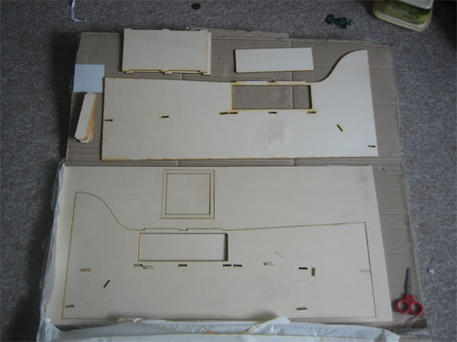 The fit between the laser cut parts was really precise, all the parts were able to dry fit together with no filing or adaptations needed. The sheet also seemed to be very close to the 4mm nominal, I'd included little bumps on the slots to take out tolerances of the tabs and these gave a good friction fit. I've not had contact with laser cutting before and I confess I was really surprised by how accurate and easy it all was. 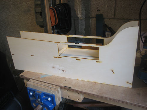 The design as it stands does not include any laser cut plastic for the windows in the test section; I ended up making these from polystyrene sheet I had left over from another project. Ponoko carry acrylic sheets and it would be easy to design windows to fit. The ones I made were cut with a jigsaw and finished by hand with a file using the ply panels cut from the window holes as templates. I made some rectangular pieces that I glued over the edges of the panels, leaving an overlap that I could use to drill and then put a screw through into the wood behind. The tunnel uses cardboard to make the top and bottom sides of the duct, simply glued into place. To seal some gaps between the cardboard and the plywood I used some decorators caulk sealant. I discovered quite quickly that I hadn't really put enough thought into the fan mounting. In the end I used the piece I'd had laser cut andwiched together with a part cut from the plywood sheet that was not laser cut. If I had time to iterate the design I'd improve this part. The motor bolts into place with a metal fan grille over the top to protect fingers from the blades. In the end I also added some lights to the test section - I used some flat LED patches that I'd bought at Ikea ages ago for our kitchen (they turned out to be rubbish for the kitchen but perfect for the tunnel). Lighting makes it much easier to see what's going on in a demonstration and I'd recommend it. Models - the best laid plans... I'd intended to be able to measure pressure changes around a wing section and demonstrate them using an array of u-tube manometers. The idea would be to measure pressure all around a wing section and then display it to show the low pressure on the top and the higher pressure on the bottom of a wing and then show how this changes when the wing stalls (when flow can no longer follow the top surface of the wing - for more explanations on this and more please see this excellent site). I was a little unsure that this was a good idea since the 'low pressure on the top sucks the aircraft into the air' model for lift generation isn't my favourite but I thought it would make a good demo if nothing else. So: I needed a wing section, here I turned to Shapeways. I designed a wing section with integral pressure tap tubes and had it 3D printed. This is a brilliant use for 3D printing, it's absolutely what it's best at. The first time I met 3D printing was at the low-speed wind tunnel at work where they hard started to use it to make parts for wind tunnel models. If you want to measure pressure around a model you need a tube that will allow you to access the surface at that point, this is known as a pressure tapping. A hole in the surface of the model will be connected, via a tube, to a pressure guage. The really nice thing about 3D printing is that you can build all of these tubes and holes in the model in one piece and save a huge amount of work. My wing turned out really well except in one way - it didn't work. 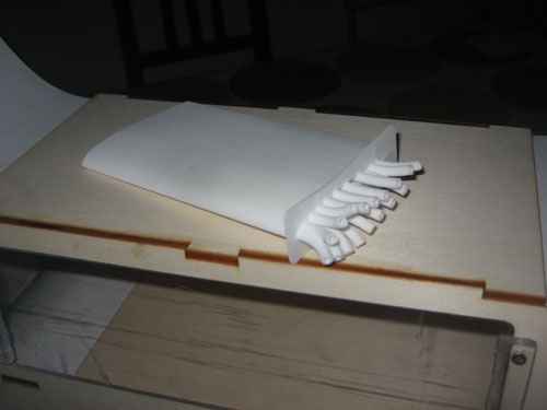 It didn't work for a few reasons: Why it didn't work #1 - wrong choice of material The material I chose, without really thinking, was the Shapeways "white, strong and flexible" Nylon plastic. This is normally excellent and quite cheap. However it's also laser sintered from powder and some of the powder that wasn't melted together wouldn't fully come out of all of the fine tubes; blocked like this the pressure tappings would never work. The other problem is that this material is slightly porous and the leaks this would allow would be a disaster for the pressure measurements. If you want to do something like this use some of the liquid-based non-porous materials (I think "transparent detail" might be suitablem, check the material details of your 3D printer for a final check). Why it didn't work #2 - wrong speed & rubbish manometers When I finally realised that my beautiful pressure tapped wing wouldn't work I hacked something (literally) out of softwood to test if I could have got a measureable pressure change. Turns out that I wouldn't have anyway. The speeds I was getting in the tunnel were not large and so the pressure changes that I could get were correspondingly small. The manometers I built to test simply wouldn't measure pressure changes that small. It might be possible to measure these pressures but not with homemade equipment (at least not homemade by me anyway). Why it didn't work #3 - where I become even more embarassed... To provide the final nail in the pressure-measurement coffin I built the wing as a mirror image of what I really wanted. That's all I have to say about that. Models - what I did in the end What I actually did was to adapt the very first 3D print I'd ever had made - a model of a wacky aircraft I came up with as a demonstration of how you can learn from even the silliest-looking concept. I'd put this in the tunnel with a stand made from polystyrene and show some of the flow patterns around the aircraft using a wool tuft. 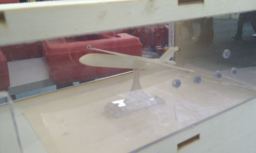 The above photo doesn't really give you the sense of the silliness of this model so I'll show a three-view below: 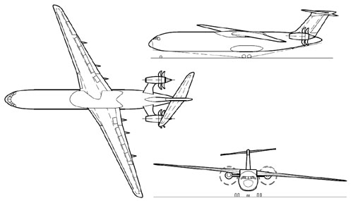 It really is very silly and no-one would ever want to build such a thing, but it has some subtle good points to go with its glaringly obvious bad points; how long it takes for people to work out what these are is always an interesting measure of how they approach a problem... To my suprise this worked a treat! The model sits at incidence in the tunnel and it's possible to prove that it's producing lift by checking behind the wing tips - the wool tuft happily spins around showing the tip vortices. It's also possible to show the slight upwash in front of the wing and the downwash behind the wing. The lights in the tunnel make the model and the motion of the wool tuft (just a stick with a bit of cotton and a tuft of wool on the end) really clear. 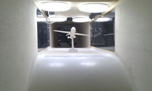 (I'm quite pleased with this picture into the test section - it's quite hard to see the scale and could easily be a lot bigger than it is :) Files So you think you want a wind tunnel? All the files that you might want to make this one are here. Because I've finished with the project and I hope you might be able to get more use out of it I'm releasing all of the files linked to below under a Creative Commons Attribution-ShareAlike license. For full terms please follow the link above, but in summary: you are free to share and remix the work I've done as long as you credit me and license the work you do under the same terms. Wind tunnel - Zipped PostScript (*.eps) files for Ponoko and source Inkscape SVGs are here Wing model (that didn't work so well for me, your mileage may vary) zipped *.stl file is here For the power supply something like this would probably work For the fan, you might try something like this but go for more power if you can (within the computer fan realm Delta fans are probably the most powerful I've seen) - remember to get a fan guard! I'm not releasing the design or 3D printing file for the aircraft because the model required some adaptation before I could use it (clipping the wings back to a smaller span, for example) and its wacky configuration wouldn't help most people to explain the principles involved. If there's a big demand I might be able to set something else up, feel free to tweet something to @fastness or send me a mail. |
fastness - Iain Banks Graphics

All of the content from my Iain M Banks website, now shifted to be a section in this one
fastness
- Links & Resources:
Processing:An open source programming tool aimed at artists, engineers and designers. Simple, light and Java-based with a wealth of libraries and a strong user community
Shapeways:
3D printing for the masses - plastics and metal to your design or team up with a desigenr to personalise a design with a 'co-creator'. Visit my Shapeways shop for some things I've designed.
Meshlab:
MeshLab is an open source, portable, and extensible system for the processing and editing of unstructured 3D triangular meshes
Blender:
Blender is the free open source 3D content creation suite, available for all major operating systems under the GNU General Public License
Gimp:
GIMP is the GNU Image Manipulation Program. It is a freely distributed piece of software for such tasks as photo retouching, image composition and image authoring. It works on many operating systems, in many languages
Inkscape:
An Open Source vector graphics editor, with capabilities similar to Illustrator, CorelDraw, or Xara X, using the W3C standard Scalable Vector Graphics (SVG) file format
Ponoko:
Retail laser cutting outlet with centres in New Zealand, USA, Germany, Italy and the UK (if not more by now)
Eclipse:
Java development environment